Several additional TNX-01 boardsets have been found in the wild over the past few months, and we’re happy to hear that Sky Skipper may eventually live on with additional owners. To think that we may someday have a registry of additional working games and their owners is a very exciting prospect and will only happen if these additional boardsets can be converted back to working status. With that, some work is already underway to reverse-engineer these additional boardsets and de-convert them from Popeye and back to playing Sky Skipper, as they were originally designed to do.
In a move to help that effort, we’ve posted below some pics of our working PCB stack – both for reference/documentation purposes and for making sure that what we have it being shared as best as we can. We’ll include additional details on the working PCB stack as we can obtain it and as the efforts of others continue through the de-conversion process.
Click on the thumbnails for the full-size originals.
| Board | Picture | Notes |
| Timer
|
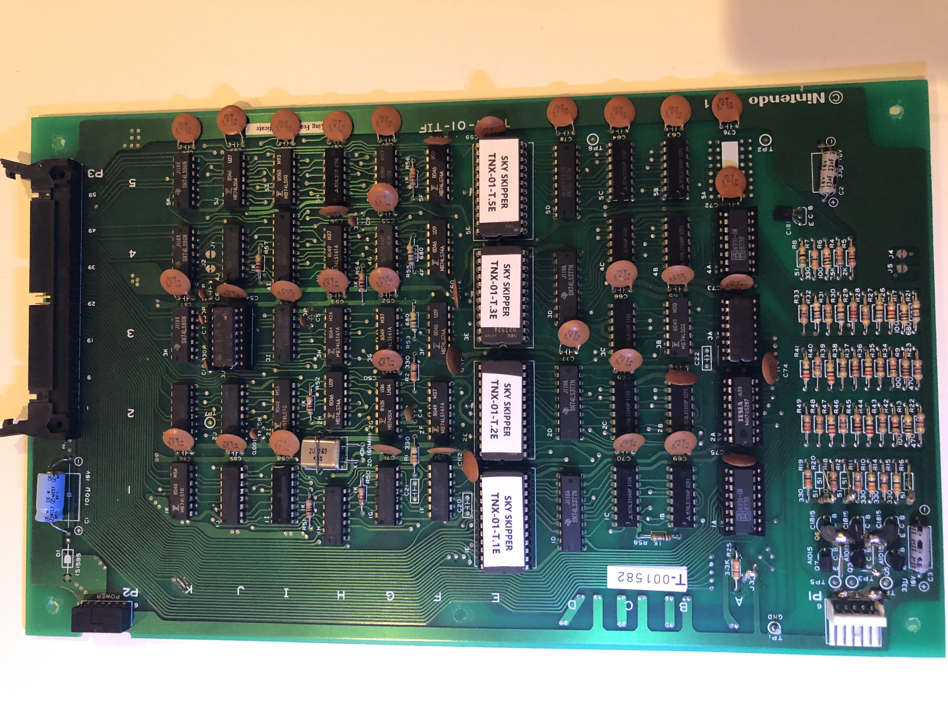 Front shot #1 Front shot #1 |
This is the smallest of the boards on the stack and is located on the back side of the PCB mounting plate. |
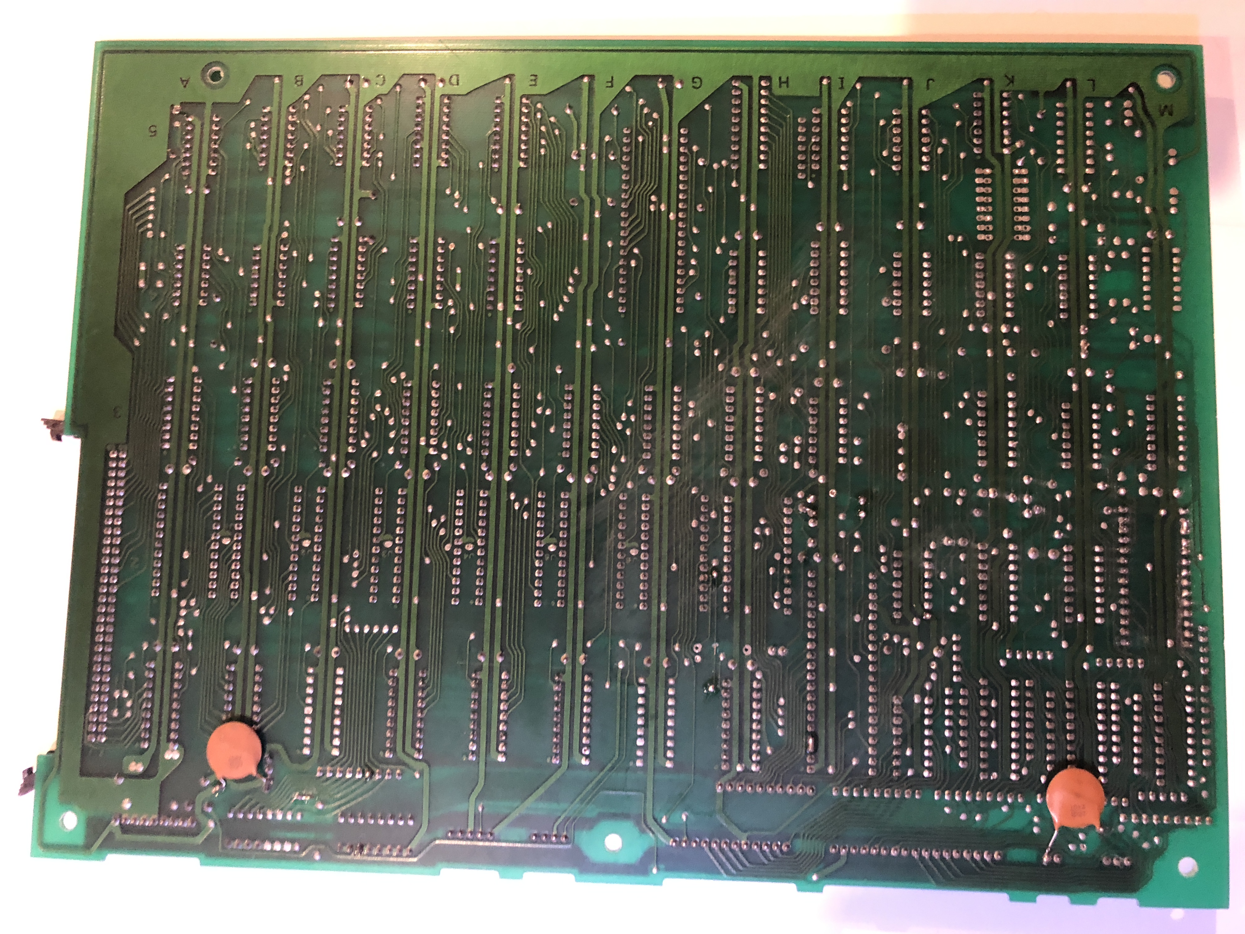
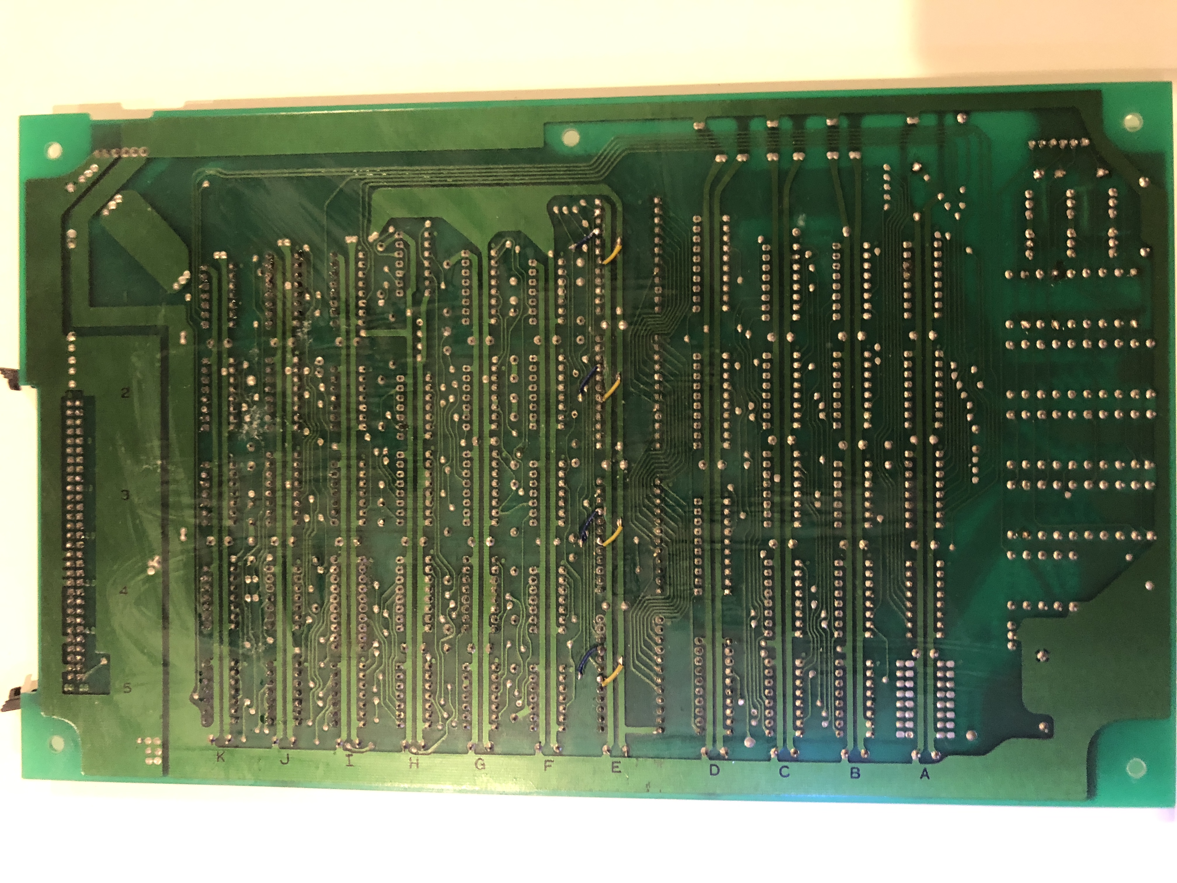 Back shot #1 Back shot #1 |
Note the series of jumpers on the back of the board. | |
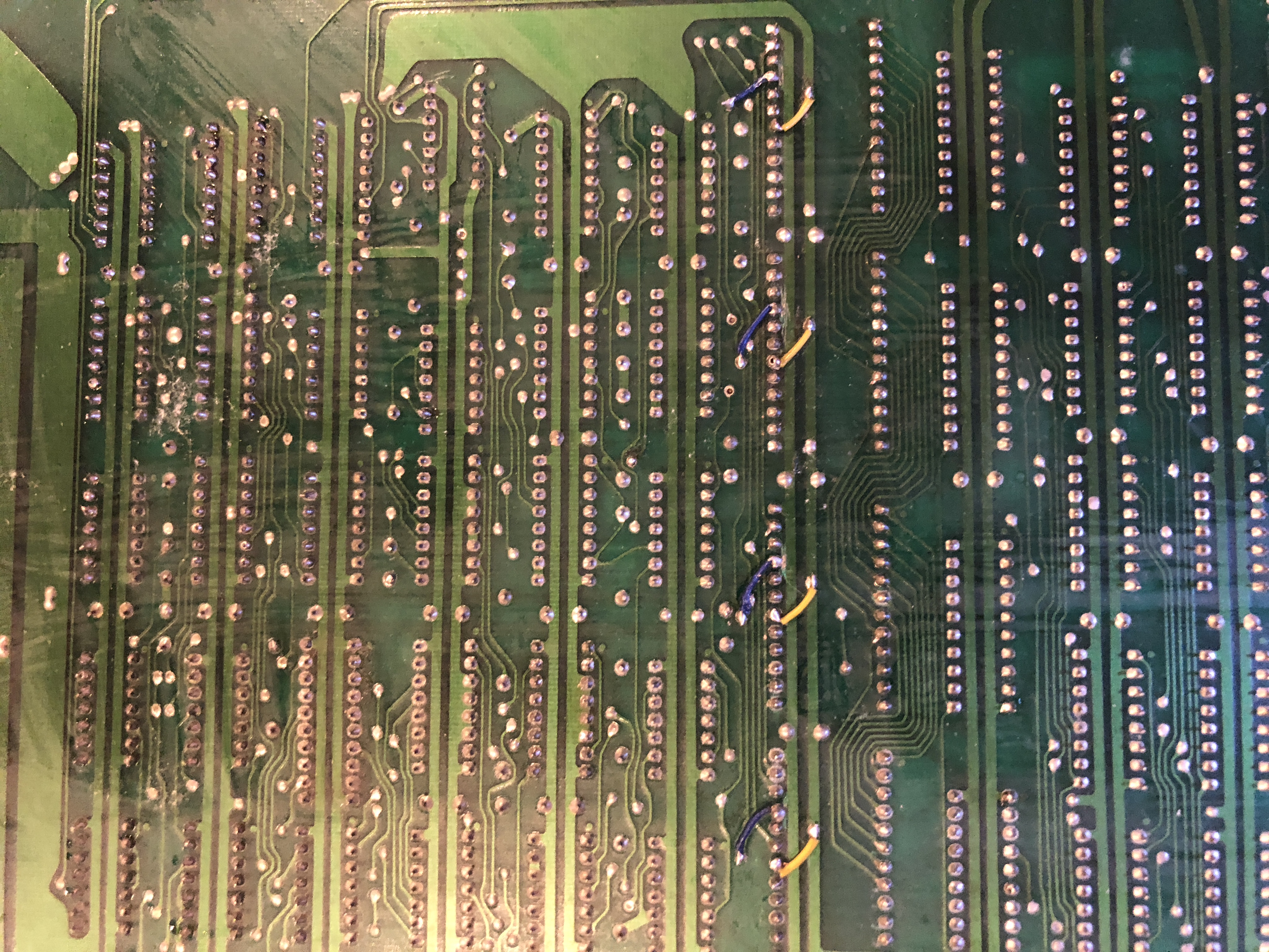
Back shot #2 |
Closeup of the jumper wires and their connection points. | |
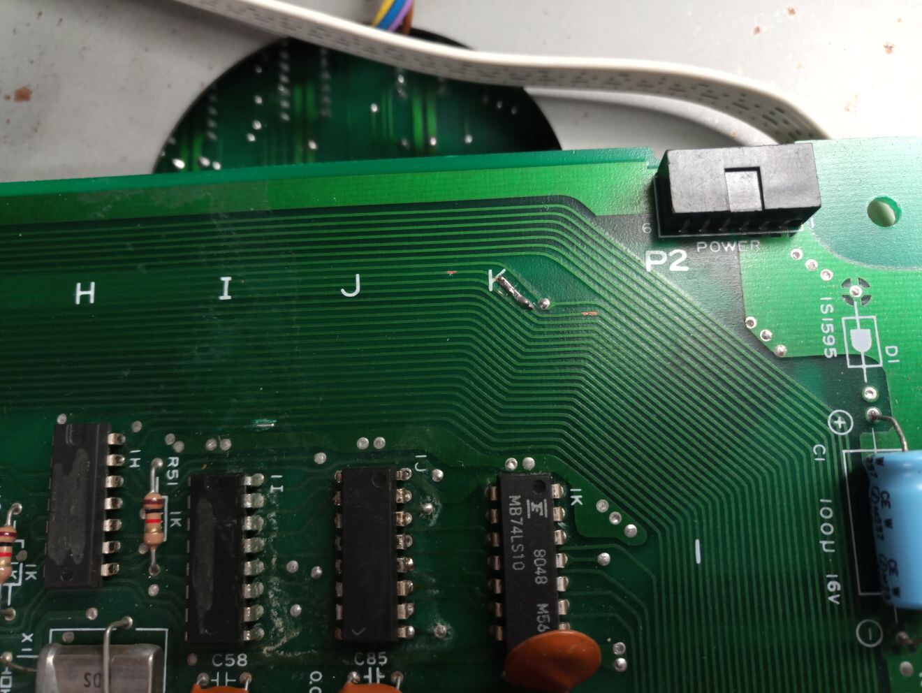
Front shot #2 |
Close-up of the trace work done in the ‘K’ column of the board matrix. | |
| CPU | 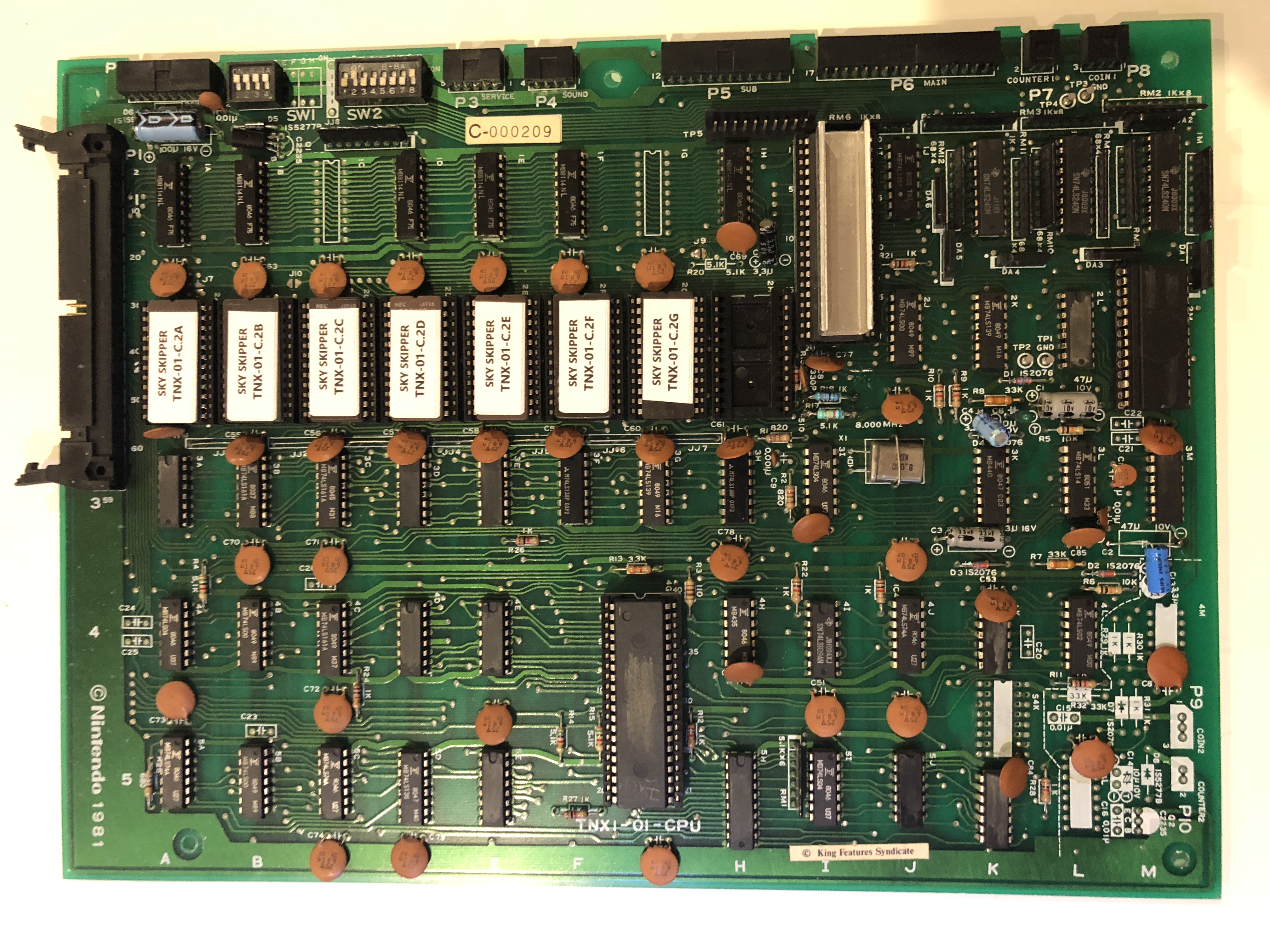 Front shot #1 Front shot #1 |
|
 Back shot #1 Back shot #1 |
||
| Video | 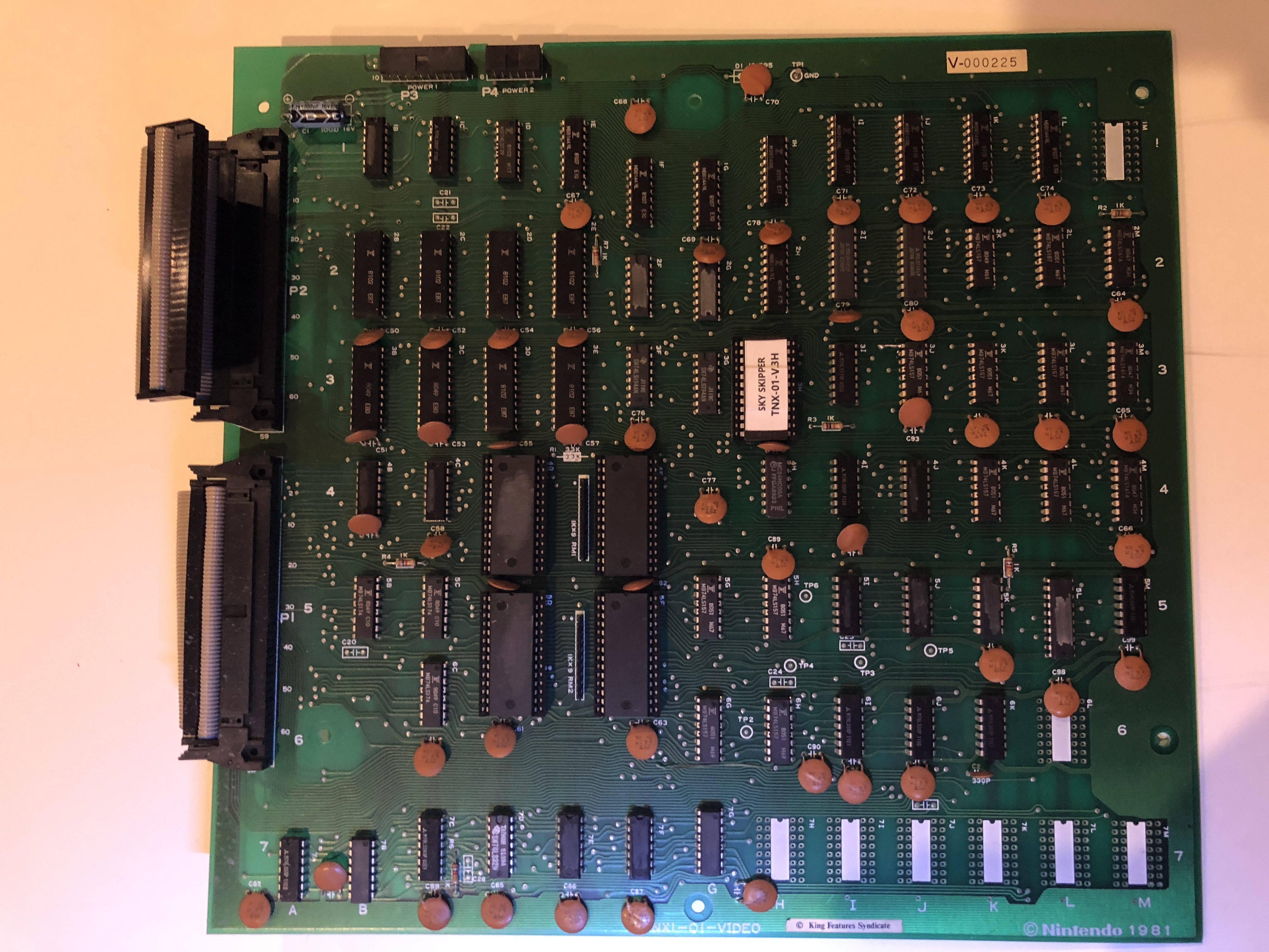
Front shot #1 |
|
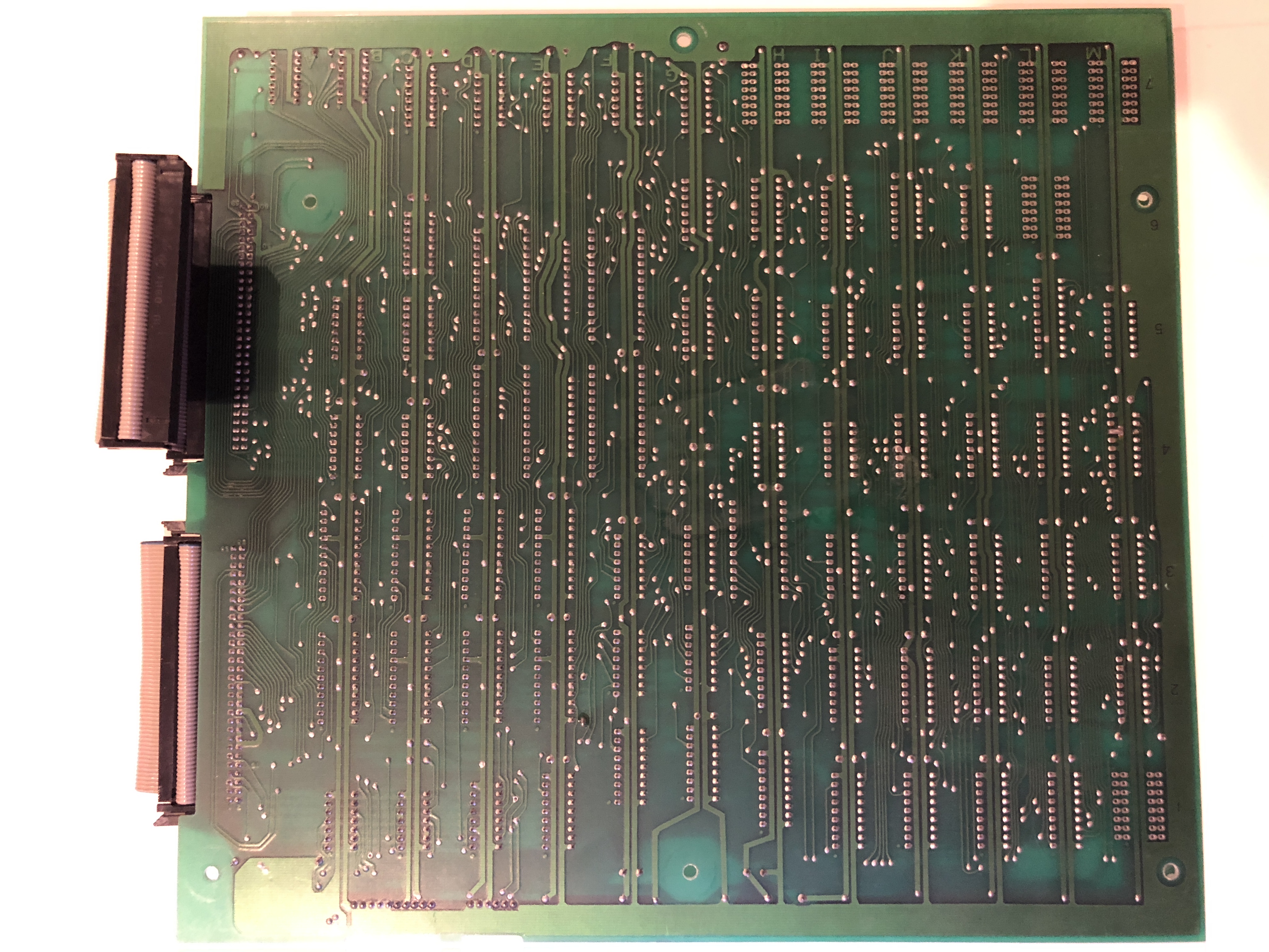 Back shot #1 |
A few additional notes
- The pictures above are from Whitney’s boardset. This is the PCB stack that was running at the Southern-Fried Gameroom Expo at the US reveal in June 2017.
- The ROMS have been re-labeled from earlier pictures. This was done in late June of 2017, as I had the board stack split apart to re-burn a couple of ROMS that had become faulty and weren’t checksumming properly.
- On the CPU board – there is a 17-pin connector labeled ‘MAIN’. This is the harness connector from the control panel and in order to get the ‘Speed’ button to work properly, an additional wire needs to be run from Pin 9 on this connector to the ‘Speed’ button on the control panel. A Popeye harness (dropped in, with no modifications) works perfectly for this game, with the one exception of the speed button not working properly. I later plan on connecting the additional wire to the edge connector on the harness to make disconnecting the PCB from the game easier (and to make it cleaner looking) but for now this additional jumper wire will provide a fully-functioning control panel.

What say you? – Recent Comments